3ds Max Tutorial 001: Cubed
Introduction
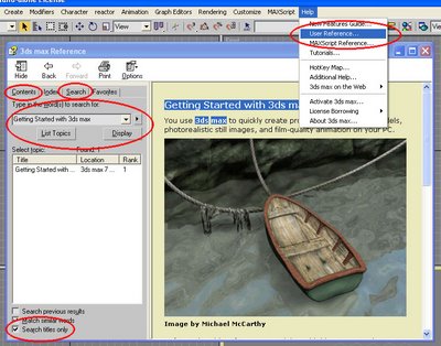
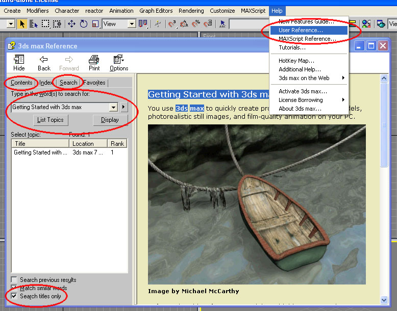
This beginners’ tutorial outlines three ways of making a cube, as an introductory overview of the way Discreet 3D Studio Max approaches 3d modelling. This tutorial will briefly introduce the reader to a number of versatile tools in 3ds Max, but will not describe any of them in any great detail. 3ds Max comes with a very good online reference, found under Help > User Reference…, and the reader is encouraged to look up certain help topics in the user reference. These topics will be highlighted in bold, and can be searched for in the user reference with the “Search titles only” option checked. Information that can be easily found in the user reference will not be covered in this tutorial.
Readers who are entirely new to 3ds Max are encouraged to go to the user reference and read the “Getting Started with 3ds Max” chapter. Because of the amount of reading involved, this tutorial may actually take a very long time to complete. However, readers are free to stop after modelling the first or the second cube, as each cube represents a particular approach to modelling which may be sufficient for the reader on its own.
This tutorial was created with reference to version 7 of 3ds Max, but it should apply to most other versions as well.
Box Primitive
To start with, create a Box Primitive, which is a Standard Primitive (if you can’t work out how to do things, remember to look up the words in bold in the user reference). Do not worry about the Creation Parameters for the box at the moment, although it might be a good idea to look up how Parametric modelling works.
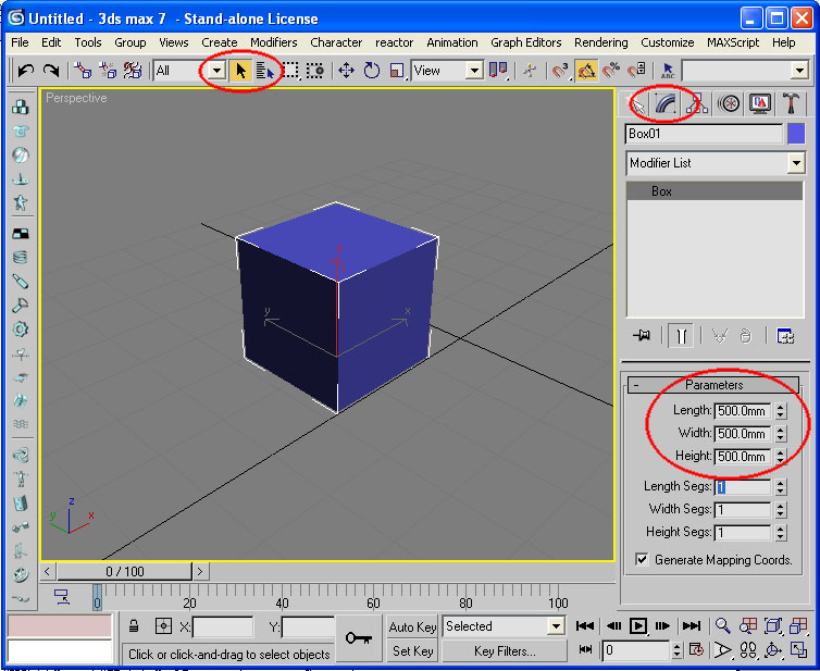
Once you’ve created the box, select it using Select Object, and go to the Modify Panel. Under “Parameters”, give the box the same measurements for “Length”, “Width”, and “Height” (I made mine 500mm). Now we have our first cube.

Spline-Extrude
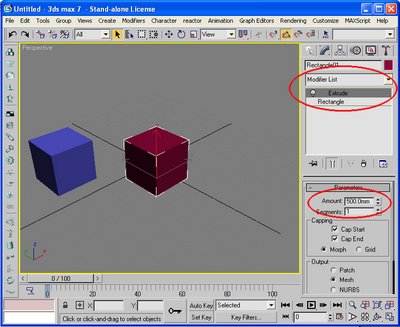
Next, use the Viewport Controls to find some more space if necessary, and make a Rectangle Spline (and maybe find out what Shapes and Splines are, too, while you’re at it). Go to the Modify Panel and make the “Length” and “Width” of the rectangle the same as your cube. Using the Modify Panel, add the Extrude Modifier from the modifier list to the rectangle (at some point, you may want to familiarise yourself with the full List of Available Modifiers). Under the “Amount” parameter, enter the height of the extrusion, which would be the same as the length and the width of the rectangle since we are making a cube. Now we have a second cube.
Spline-Surface
The next part gets substantially more complex, but the tools introduced are also substantially more versatile and powerful. It is highly recommended that you read the user reference entries highlighted, as well as entries on related topics. Remember that you may also un-check “Search titles only” to conduct a general search of the user reference on any topic.
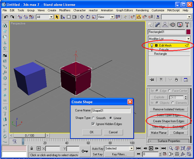
With the second cube still selected, add an Edit Mesh Modifier (also look up its cousin, the Editable Mesh Surface). Using the edge tools (Editable Mesh (Edge)), select all the edges of the cube and click “Create Shape from Edges”, select “Linear” under “Shape Type”, and click “Ok” on the dialogue box that comes up.

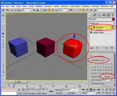
Now exit the edge tools and select the new shape. The new shape is overlapping cube two, so it may be easiest to use select by name. Select and Move the shape away from the second cube. In the Modify Panel, you will see that the shape is an Editable Spline. From the modifier list, add a Surface Modifier. You will now see what appears to be a cube with rounded edges. Add an Edit Mesh Modifier, go into the polygon tools (Editable Mesh (Face/Polygon/Element)), select all the polygons of your third cube, and under Smoothing Groups, click “Clear All”. Exit the polygon tools, and you’ll have your third cube.
Debrief
If you are new to 3ds Max and you managed to complete this tutorial with three cubes and an understanding of how you created them, then you deserve to be congratulated. Although I intended for this to be a beginner’s tutorial, I also knew that the learning curve was very steep, and that a lot of concepts were being covered very quickly. I will now go back and make some comments on what has been covered.
The first cube was the simplest, made using Geometric Primitives. Using only primitives, it is fairly easy and straightforward to sketch a model. Multiple primitives may be arranged and overlapped to increasingly complex compositions, which can be made to resemble just about anything. However, this type of modelling can quickly run into inefficiencies. For example, with complex arrangements of several dozen or several hundred overlapping primitives, it may become extremely difficult to keep track of the way the primitives relate to each other in order to change or adjust the model. Texturing and animation is difficult for the same reasons, and rendering is made inefficient by the large number of redundant polygons that are hidden by other geometry, but nevertheless has to be calculated by the renderer.
The second cube was made using the spine-extrude method, a method that is particularly useful for modelling architectural elements because of the rectilinearity of conventional architecture. Holes can be cut into slabs can be produced by nesting one closed spline within another, avoiding the use of the often unreliable Boolean Compound Object. It is also relatively easy to import plans from CAD programs like AutoCAD and extrude the lines to make a model of a building, as long as the CAD drawings are tidy and drawn with modelling in mind. The obvious limitation of this method is that it is limited to extrusions, and anything that isn’t meant to be a straight extrusion will require additional editing. The extrude is somewhat related to the Lathe Modifier and the Loft Compound Object.
The third cube introduced Surface Modelling with Editable Spline and Editable Mesh, tools that allow full control of every aspect of the model, but which also assumes full understanding of how geometry in 3ds Max works. Basically, a vertex is a defined point in space, an edge is a line between two vertices, and a face is a triangle with a vertex at each corner and joined by edges. An edge has a direction, as in from vertex 0 to vertex 1. A face also has a direction, or a Normal, meaning each face is one-sided (unlike, say, something like a piece of paper, which has two sides). The editable spline and editable mesh, along with the related Editable Patch and Editable Poly, allow the direct creation, manipulation, and deletion of vertices, edges, and faces. These are powerful tools, but they will lead to unexpected results if you do not understand how they work. It is highly recommended that you familiarise yourself with all aspects of the editable spline and editable mesh tools.
The third cube also introduces the spline-surface method of modelling, which is probably best explained by the Surface Modifier entry in the user reference. It should be noted that this method is usually used for organic, free-form modelling, and that the modelling of a cube is not usually done this way. However as shown with the cube, it is not difficult to make inorganic, rigid shapes with this method also. This method of modelling is useful for any complex shape. The most common problem the surface modifier is that it only creates surfaces where the interconnected splines form three or four sided polygons. If you find your model has missing faces after applying the surface modifier, the problem is usually that you have inadvertently created a five or more sided polygon, or that the splines are not properly connected.
I hope this tutorial has been helpful, and I wish you luck with your modelling.
Simon Chun Kwan Chui
15/6/2006
This beginners’ tutorial outlines three ways of making a cube, as an introductory overview of the way Discreet 3D Studio Max approaches 3d modelling. This tutorial will briefly introduce the reader to a number of versatile tools in 3ds Max, but will not describe any of them in any great detail. 3ds Max comes with a very good online reference, found under Help > User Reference…, and the reader is encouraged to look up certain help topics in the user reference. These topics will be highlighted in bold, and can be searched for in the user reference with the “Search titles only” option checked. Information that can be easily found in the user reference will not be covered in this tutorial.
Readers who are entirely new to 3ds Max are encouraged to go to the user reference and read the “Getting Started with 3ds Max” chapter. Because of the amount of reading involved, this tutorial may actually take a very long time to complete. However, readers are free to stop after modelling the first or the second cube, as each cube represents a particular approach to modelling which may be sufficient for the reader on its own.
This tutorial was created with reference to version 7 of 3ds Max, but it should apply to most other versions as well.
Box Primitive
To start with, create a Box Primitive, which is a Standard Primitive (if you can’t work out how to do things, remember to look up the words in bold in the user reference). Do not worry about the Creation Parameters for the box at the moment, although it might be a good idea to look up how Parametric modelling works.
Once you’ve created the box, select it using Select Object, and go to the Modify Panel. Under “Parameters”, give the box the same measurements for “Length”, “Width”, and “Height” (I made mine 500mm). Now we have our first cube.
Spline-Extrude
Next, use the Viewport Controls to find some more space if necessary, and make a Rectangle Spline (and maybe find out what Shapes and Splines are, too, while you’re at it). Go to the Modify Panel and make the “Length” and “Width” of the rectangle the same as your cube. Using the Modify Panel, add the Extrude Modifier from the modifier list to the rectangle (at some point, you may want to familiarise yourself with the full List of Available Modifiers). Under the “Amount” parameter, enter the height of the extrusion, which would be the same as the length and the width of the rectangle since we are making a cube. Now we have a second cube.

Spline-Surface
The next part gets substantially more complex, but the tools introduced are also substantially more versatile and powerful. It is highly recommended that you read the user reference entries highlighted, as well as entries on related topics. Remember that you may also un-check “Search titles only” to conduct a general search of the user reference on any topic.
With the second cube still selected, add an Edit Mesh Modifier (also look up its cousin, the Editable Mesh Surface). Using the edge tools (Editable Mesh (Edge)), select all the edges of the cube and click “Create Shape from Edges”, select “Linear” under “Shape Type”, and click “Ok” on the dialogue box that comes up.
Now exit the edge tools and select the new shape. The new shape is overlapping cube two, so it may be easiest to use select by name. Select and Move the shape away from the second cube. In the Modify Panel, you will see that the shape is an Editable Spline. From the modifier list, add a Surface Modifier. You will now see what appears to be a cube with rounded edges. Add an Edit Mesh Modifier, go into the polygon tools (Editable Mesh (Face/Polygon/Element)), select all the polygons of your third cube, and under Smoothing Groups, click “Clear All”. Exit the polygon tools, and you’ll have your third cube.

Debrief
If you are new to 3ds Max and you managed to complete this tutorial with three cubes and an understanding of how you created them, then you deserve to be congratulated. Although I intended for this to be a beginner’s tutorial, I also knew that the learning curve was very steep, and that a lot of concepts were being covered very quickly. I will now go back and make some comments on what has been covered.
The first cube was the simplest, made using Geometric Primitives. Using only primitives, it is fairly easy and straightforward to sketch a model. Multiple primitives may be arranged and overlapped to increasingly complex compositions, which can be made to resemble just about anything. However, this type of modelling can quickly run into inefficiencies. For example, with complex arrangements of several dozen or several hundred overlapping primitives, it may become extremely difficult to keep track of the way the primitives relate to each other in order to change or adjust the model. Texturing and animation is difficult for the same reasons, and rendering is made inefficient by the large number of redundant polygons that are hidden by other geometry, but nevertheless has to be calculated by the renderer.
The second cube was made using the spine-extrude method, a method that is particularly useful for modelling architectural elements because of the rectilinearity of conventional architecture. Holes can be cut into slabs can be produced by nesting one closed spline within another, avoiding the use of the often unreliable Boolean Compound Object. It is also relatively easy to import plans from CAD programs like AutoCAD and extrude the lines to make a model of a building, as long as the CAD drawings are tidy and drawn with modelling in mind. The obvious limitation of this method is that it is limited to extrusions, and anything that isn’t meant to be a straight extrusion will require additional editing. The extrude is somewhat related to the Lathe Modifier and the Loft Compound Object.
The third cube introduced Surface Modelling with Editable Spline and Editable Mesh, tools that allow full control of every aspect of the model, but which also assumes full understanding of how geometry in 3ds Max works. Basically, a vertex is a defined point in space, an edge is a line between two vertices, and a face is a triangle with a vertex at each corner and joined by edges. An edge has a direction, as in from vertex 0 to vertex 1. A face also has a direction, or a Normal, meaning each face is one-sided (unlike, say, something like a piece of paper, which has two sides). The editable spline and editable mesh, along with the related Editable Patch and Editable Poly, allow the direct creation, manipulation, and deletion of vertices, edges, and faces. These are powerful tools, but they will lead to unexpected results if you do not understand how they work. It is highly recommended that you familiarise yourself with all aspects of the editable spline and editable mesh tools.
The third cube also introduces the spline-surface method of modelling, which is probably best explained by the Surface Modifier entry in the user reference. It should be noted that this method is usually used for organic, free-form modelling, and that the modelling of a cube is not usually done this way. However as shown with the cube, it is not difficult to make inorganic, rigid shapes with this method also. This method of modelling is useful for any complex shape. The most common problem the surface modifier is that it only creates surfaces where the interconnected splines form three or four sided polygons. If you find your model has missing faces after applying the surface modifier, the problem is usually that you have inadvertently created a five or more sided polygon, or that the splines are not properly connected.
I hope this tutorial has been helpful, and I wish you luck with your modelling.
Simon Chun Kwan Chui
15/6/2006
posted by sckChui at 8:19 pm
![]()


1 Comments:
Thank you very much for such a nice explanation, It helped me a lot
Post a Comment
<< Home