Thursday, June 22, 2006

...

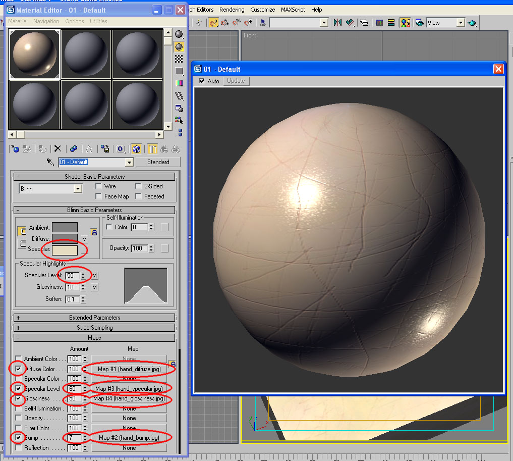
Yay, second 3ds Max tutorial. Making a material of my left hand. Weird. Quite creepy having a box that looks like flesh. But hey, that's how we do things at this blog.

Put a link to
Blender.org on the links page. Open source 3D modelling, among other things. I've only just started learning it, so don't ask me how to use it yet. The short movie Elephant's Dream is very impressive. Professional quality by any standard.

Wednesday, June 21, 2006

3ds Max Tutorial 002: Give us a Hand

Introduction
This tutorial describes the making of a material of my left hand, as an introductory overview of the way Discreet 3D Studio Max approaches materials. This tutorial will demonstrate the way different maps may be combined together to make convincing materials, but will not give a detailed, step by step guide for how this is done. 3ds Max comes with a very good online reference, found under Help > User Reference…, and the reader is encouraged to look up certain help topics in the user reference. These topics will be highlighted in bold, and can be searched for in the user reference with the “Search titles only” option checked. Most importantly, the user reference explains all the tools in Max button by button, so this is something that I will not be doing. Instead, I will refer the reader to the user reference.

This tutorial was created with reference to version 7 of 3ds Max, but it should apply to most other versions as well. As a note, it to me 45 minutes to create this hand material from scratch, using Adobe Photoshop and 3d Studio Max.


Know Your Tools
If you are new to materials in 3ds Max, then you have a bit of reading to do. First, go and look up “Material Editor, Materials, and Mapping” in the user reference. After that, follow the link to Designing Materials, which gives an outline of the workflow involved in making materials in Max. It probably goes into more depth then you need to start with, so just read it and don’t worry if you don’t understand everything. Next, look up Material Editor and familiarise yourself with that window. At this point you can also look up Types of Materials to see what’s on offer, but for this tutorial we’ll only be looking at the Standard Material, so make sure you read up on that. At the bottom of that entry, there are further links to sub-entries, which are useful to read. The most important is the Maps Rollout (Standard Material), and at the bottom of that entry are more links again, this time to the different types of maps. I highly recommend you reading up on all of them, but the ones that are dealt with in this tutorial are Diffuse Colour Mapping, Specular Level Mapping, Glossiness Mapping, and Bump Mapping.

Once you’ve read all that, you’ll know more than what you need to know to start making materials in Max. In fact, it may be a good idea for you to try out some of the tools you’ve just read about. But if you keep reading, I’ll tell you about how I make a material of my left hand.


Learning to Look
The secret to making realistic materials is learning to look at things closely. If you’re not interested in realistic materials, you’ll still need to understand clearly what you want to make. I chose to make a material of my left hand for this tutorial because most people have at least one hand on hand to look at, and I will ask you to look very closely at yours right now.

Looking at the palm of my hand, the first things I notice are the creases in the skin. Next I notice that the colour of my palm is generally a yellowish pink, although the tone is not uniform. I can also see faint blue-green veins beneath the skin. The creases in the skin are generally a darker tone than the surrounding flesh. Next, I see that the surface of the skin is somewhat glossy, and as I move my hand around, I can see the specular reflection of the light highlighting the texture and creases.

Having looked at my hand closely, I can now translate what I see into the different maps I need to make. I know that the diffuse colour component is the non-uniform yellowish pink with the blue-green veins and slightly darker creases. I know that the specular level and glossiness components describe how the specular reflection of the glossy parts of my palm highlights the textures. Lastly, I know that the bump component describes the slight grooves formed by the creases. Knowing these things, I drew some maps in Photoshop.

First, I used the brush tool to draw the diffuse map without the creases of the palm. Then I drew the bump map, again using the brush tool but with a much small brush size. I then adapted the bump map to create the specular map, which is basically the same thing but with lower contrast. I then used this map again and adapted it to make the creases in the diffuse map. Then I adapted the bump map again for the glossiness map, adding noise using the Add Noise filter in Photoshop. Actually, it wasn’t quite as straightforward as that. Originally I didn’t have the creases on the diffuse map and the noise on the glossiness map, but I added them after I tried them out in 3ds Max and found them unsatisfactory. Making materials always involve an element of trial and error, and the ability to know how to fix something that doesn’t look right is a matter of understanding how the tools work.


Show Me Some Skin
Once the maps are made, it is simply a matter of putting them in the right slots in the material editor and adjusting the amounts of each map. Below is a screenshot of the material editor after I’ve set everything up, with the changes from the default settings highlighted and a magnification of the sample slot. Once again, working out the amounts for each map is a matter of trial and error, trying out different values to see what works and what doesn’t.


The following are two views of the material applied to a box. The first view has the camera angled to catch the specular reflection from the light; the second view is angled away from the specular reflection.


Below are each of the four components rendered separately by turning off the others. You’ll notice that the specular level, glossiness, and bump components don’t do very much on their own, and need to be combined to have much affect. It is often better to build up the texture of a material using many subtle effects than to try to use only one map.


Debrief
That ends our brief overview of the Standard Material. As you probably gathered by now, materials in 3ds Max can simulate the appearance of objects in the real world, but otherwise they have very little in common. In reality, all the diffuse, specular, and glossiness components of an object are in fact the result of electromagnetic radiation interacting with a collection of molecules at the atomic level, reflecting off those molecules in varying ways. In Max, that interaction is approximated by calculations, components of which may be turned on and off. Therefore, it is important to not expect materials in Max to behave the way one might expect them to behave in the real world, but rather understand that it is a whole other system with different rules.

As I said earlier, the secret to making realistic materials is learning to look at things closely. If I ask you to describe to be a piece of A4, laser quality paper, and you tell me it’s white, then you’re not looking closely enough. Looking at a piece of A4 paper right now, I can tell you that it’s not entirely uniform white, that it has a certain texture formed by the wood fibres that make up the paper, and that it has a certain specular component. In brief, I would say that it is very faintly splotchy. Do not underestimate such subtleties; the human mind is very good at feeling uncomfortable when something isn’t quite right, even if it can’t determine exactly what’s wrong. People often criticise poor computer renders as being “flat”, “dead”, or “plastic”. This is precisely because the subtleties have been overlooked.

Once you have come to grips with the standard material, you may like to have a look at the Raytrace Material, the Architectural Material, and the Ink ‘n Paint Material. Raytrace and Architectural materials allow more effects, most notably reflections, but are also more computationally intensive at render time. It is generally advisable to use the standard material wherever possible, and only use the more advanced materials when you want specific effects that are not possible with the standard material. The Ink ‘n Paint Material generates cartoon-like effects.

I hope this tutorial has been helpful, and I wish you luck with your materials.


Simon Chun Kwan Chui
21/6/2006

Thursday, June 15, 2006

...

So I finally put something vaguely useful on my blog. It's a 3ds Max tutorial. I would have done it sooner, but I was playing computer games. Haha.

3ds Max Tutorial 001: Cubed

Introduction
This beginners’ tutorial outlines three ways of making a cube, as an introductory overview of the way Discreet 3D Studio Max approaches 3d modelling. This tutorial will briefly introduce the reader to a number of versatile tools in 3ds Max, but will not describe any of them in any great detail. 3ds Max comes with a very good online reference, found under Help > User Reference…, and the reader is encouraged to look up certain help topics in the user reference. These topics will be highlighted in bold, and can be searched for in the user reference with the “Search titles only” option checked. Information that can be easily found in the user reference will not be covered in this tutorial.

Readers who are entirely new to 3ds Max are encouraged to go to the user reference and read the “Getting Started with 3ds Max” chapter. Because of the amount of reading involved, this tutorial may actually take a very long time to complete. However, readers are free to stop after modelling the first or the second cube, as each cube represents a particular approach to modelling which may be sufficient for the reader on its own.

This tutorial was created with reference to version 7 of 3ds Max, but it should apply to most other versions as well.


Box Primitive
To start with, create a Box Primitive, which is a Standard Primitive (if you can’t work out how to do things, remember to look up the words in bold in the user reference). Do not worry about the Creation Parameters for the box at the moment, although it might be a good idea to look up how Parametric modelling works.

Once you’ve created the box, select it using Select Object, and go to the Modify Panel. Under “Parameters”, give the box the same measurements for “Length”, “Width”, and “Height” (I made mine 500mm). Now we have our first cube.


Spline-Extrude
Next, use the Viewport Controls to find some more space if necessary, and make a Rectangle Spline (and maybe find out what Shapes and Splines are, too, while you’re at it). Go to the Modify Panel and make the “Length” and “Width” of the rectangle the same as your cube. Using the Modify Panel, add the Extrude Modifier from the modifier list to the rectangle (at some point, you may want to familiarise yourself with the full List of Available Modifiers). Under the “Amount” parameter, enter the height of the extrusion, which would be the same as the length and the width of the rectangle since we are making a cube. Now we have a second cube.


Spline-Surface
The next part gets substantially more complex, but the tools introduced are also substantially more versatile and powerful. It is highly recommended that you read the user reference entries highlighted, as well as entries on related topics. Remember that you may also un-check “Search titles only” to conduct a general search of the user reference on any topic.

With the second cube still selected, add an Edit Mesh Modifier (also look up its cousin, the Editable Mesh Surface). Using the edge tools (Editable Mesh (Edge)), select all the edges of the cube and click “Create Shape from Edges”, select “Linear” under “Shape Type”, and click “Ok” on the dialogue box that comes up.


Now exit the edge tools and select the new shape. The new shape is overlapping cube two, so it may be easiest to use select by name. Select and Move the shape away from the second cube. In the Modify Panel, you will see that the shape is an Editable Spline. From the modifier list, add a Surface Modifier. You will now see what appears to be a cube with rounded edges. Add an Edit Mesh Modifier, go into the polygon tools (Editable Mesh (Face/Polygon/Element)), select all the polygons of your third cube, and under Smoothing Groups, click “Clear All”. Exit the polygon tools, and you’ll have your third cube.


Debrief
If you are new to 3ds Max and you managed to complete this tutorial with three cubes and an understanding of how you created them, then you deserve to be congratulated. Although I intended for this to be a beginner’s tutorial, I also knew that the learning curve was very steep, and that a lot of concepts were being covered very quickly. I will now go back and make some comments on what has been covered.

The first cube was the simplest, made using Geometric Primitives. Using only primitives, it is fairly easy and straightforward to sketch a model. Multiple primitives may be arranged and overlapped to increasingly complex compositions, which can be made to resemble just about anything. However, this type of modelling can quickly run into inefficiencies. For example, with complex arrangements of several dozen or several hundred overlapping primitives, it may become extremely difficult to keep track of the way the primitives relate to each other in order to change or adjust the model. Texturing and animation is difficult for the same reasons, and rendering is made inefficient by the large number of redundant polygons that are hidden by other geometry, but nevertheless has to be calculated by the renderer.

The second cube was made using the spine-extrude method, a method that is particularly useful for modelling architectural elements because of the rectilinearity of conventional architecture. Holes can be cut into slabs can be produced by nesting one closed spline within another, avoiding the use of the often unreliable Boolean Compound Object. It is also relatively easy to import plans from CAD programs like AutoCAD and extrude the lines to make a model of a building, as long as the CAD drawings are tidy and drawn with modelling in mind. The obvious limitation of this method is that it is limited to extrusions, and anything that isn’t meant to be a straight extrusion will require additional editing. The extrude is somewhat related to the Lathe Modifier and the Loft Compound Object.

The third cube introduced Surface Modelling with Editable Spline and Editable Mesh, tools that allow full control of every aspect of the model, but which also assumes full understanding of how geometry in 3ds Max works. Basically, a vertex is a defined point in space, an edge is a line between two vertices, and a face is a triangle with a vertex at each corner and joined by edges. An edge has a direction, as in from vertex 0 to vertex 1. A face also has a direction, or a Normal, meaning each face is one-sided (unlike, say, something like a piece of paper, which has two sides). The editable spline and editable mesh, along with the related Editable Patch and Editable Poly, allow the direct creation, manipulation, and deletion of vertices, edges, and faces. These are powerful tools, but they will lead to unexpected results if you do not understand how they work. It is highly recommended that you familiarise yourself with all aspects of the editable spline and editable mesh tools.

The third cube also introduces the spline-surface method of modelling, which is probably best explained by the Surface Modifier entry in the user reference. It should be noted that this method is usually used for organic, free-form modelling, and that the modelling of a cube is not usually done this way. However as shown with the cube, it is not difficult to make inorganic, rigid shapes with this method also. This method of modelling is useful for any complex shape. The most common problem the surface modifier is that it only creates surfaces where the interconnected splines form three or four sided polygons. If you find your model has missing faces after applying the surface modifier, the problem is usually that you have inadvertently created a five or more sided polygon, or that the splines are not properly connected.

I hope this tutorial has been helpful, and I wish you luck with your modelling.


Simon Chun Kwan Chui
15/6/2006

Saturday, June 03, 2006

...

Ok, got my CV up. Took a while. End of semester: exams and final hand-ins and all that.

I had originally planned to have a much bigger "Academic" section in my CV where I would describe all the stuff I've been doing at university, but I realised that it would turn by CV into a small book, and that it would take me quite a while to put together. I guess that means I'll put a "portfolio" section on my blog, and put all my work there instead. Host the PDFs on the Orcon account.

Good plan.

Curricula Vitae

CV 3/6/2006
Personal Details:

Name: Simon Chun Kwan Chui
Email:
sckchui@ihug.co.nz
Personal Website: http://sckchui.blogspot.com


Personal Statement:

I am currently in the final year of my professional Bachelor of Architecture degree at the University of Auckland, and I am looking for employment for when I finish my degree. In my architectural education I have spent much time considering the ethics of architecture and the politics of architecture, exploring these subjects through the design of low-cost social housing, a prison facility, a clandestine underwater nuclear reactor (satirical proposal), and others. For my final architecture school design project, I would like to explore the relationship between architecture and all other human endeavours, to identify and, perhaps, to redefine the scope and purpose of architecture in our unending quest to survive and to thrive.


Employment History:

2006-Current
Architectural Computing Teaching Assistant.
School of Architecture and Planning, University of Auckland

In this role, I am mostly involved in informal tutorials with students, teaching practical computing skills and techniques, as well as discussing general concepts and strategies for using the computer effectively. Software covered in the teaching include Macromedia Flash, Adobe Audition, Adobe After Effects, Adobe Illustrator, Adobe Photoshop, Autodesk AutoCAD, Autodesk 3D Studio Max, Softimage XSI, Microsoft Office, and others.


2005-Current
Academic Mentor
The Schools Partnership Office, University of Auckland

In this role I help two University scholarship winners in the architecture school maintain a Grade Point Average of 6 or above, which is the condition they must meet in order to continue receiving their scholarship. To this end, I give them general advice on all aspects of their studies, including such things as clarifying their learning objectives and demonstrating techniques for producing high quality work.


2005
Computer Aided Studio Helpdesk
School of Architecture, University of Auckland

The CAS Helpdesk role provides general troubleshooting and advice on the software provided in the Architecture Studios in the School of Architecture. The software includes a range of commercial architectural draughting, 3D modelling, image manipulation, video editing, and presentation packages.


2005
IT Helpdesk
National Institute of Creative Arts and Industries IT, University of Auckland

The IT Helpdesk role provides general troubleshooting for the faculty computer labs, as well as minor routine maintenance on the lab printers.


2004-2005
CAD Operator
Aluminium Systems New Zealand Limited

In this role I was responsible for updating an Export Sales Catalogue of aluminium window and door joinery. The manual was compiled almost entirely in Autodesk AutoCAD, and the work involved reformatting all the pages, as well as drawing installation details for new products and updating some old ones. Especially important was the addition of installation details for concrete buildings to supplement the details for timber framed buildings from the old manual.


2004-2005
Digital Visualisation
Science Intermedia Network Environment (SINE), University of Auckland

Working on the Embodied Time(-) Project with Julainne Sumich, Bruce MacDonald, Kevin Novins, Hsu Han Chiang, Jamie Kydd and James van As, I was tasked with visualising some conceptual processes, as a precursor to the development of a computer simulated environment. This involved 3D modelling and presentation work, using Discreet 3D Studio Max, Adobe After Effects, and Adobe Photoshop.


2002-2003
Architectural Draughting
Heslop Design

Working under the supervision of Bruce Heslop, I was mainly given the task of preparing architectural drawings for various residential projects using VectorWorks. I also assisted with site measurement, and I designed and built the Helsop Design website.


Current Professional Memberships:

New Zealand Institute of Architects: Student member


Academic History:

2005-2006
Bachelor of Architecture (active in programme)
University of Auckland

2002-2004
Bachelor of Architectural Studies
University of Auckland

2001
New Zealand University Bursary: A Bursary, with a Scholarship in English
Pakuranga College, Auckland


Other Interests:

Modos: 06 Collection:

Modos is a yearly publication organised by the final year architecture students at the University of Auckland to showcase our work to the public. This year, 2006, being my final year, I am working with a group of my peers to organise this year’s publication.


WAYD:

WAYD stands for What Are You Doing, and is a periodical created by the architecture students at the University of Auckland as an internal forum for the presentation and discussion of student work. I was involved in the initial conception and the first few issues of the periodical, but I have given the work over to students in the lower years who will continue the work after I leave the school.


Habitat for Humanity Auckland University Chapter:

Another student initiative at the School of Architecture, I assist when the opportunity arises.